This device makes a communication channel between two ordinary Swedish telephone sets. But each phone has
to be equipped with an 'R'-button. (The 'R'-button can be placed down to the left on a phone.) Without using the
public phone network, you would be able to dial the other phone and make a conversation. While you only can
dial one other telephone, the ringing process works something like this:
The procedure at the ringing process
1. In the beginning all telephone receivers should be hanged up.
2. The one that will make a phone call, this person pick up his phone.
3. You press the 'R'-button and the other phone is ringing.
4. The other person is answering and it stops ringing.
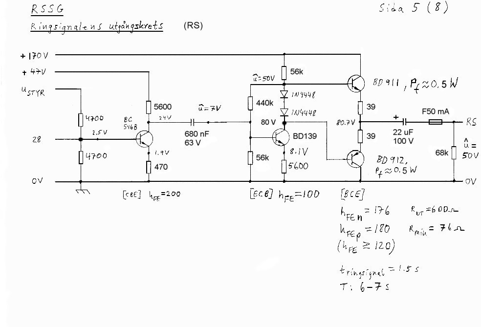
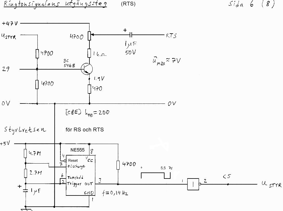
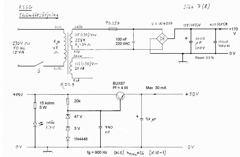
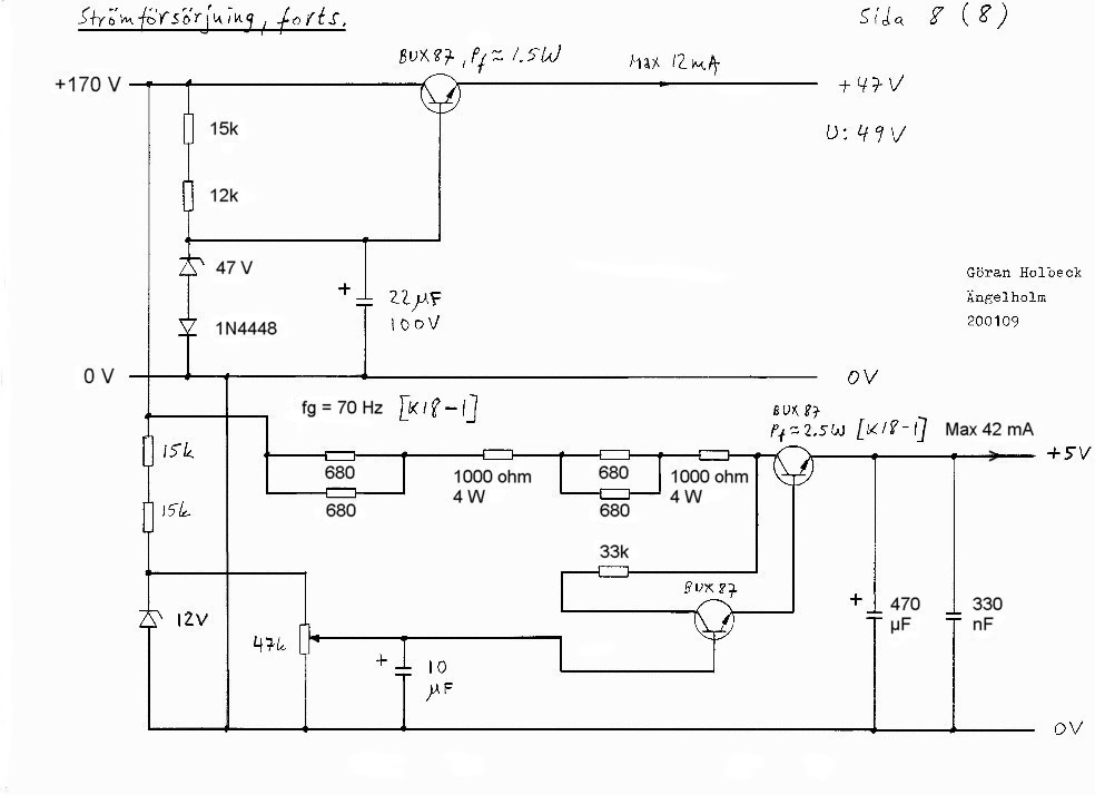
Please look at the survey diagram and all the other diagrams.
Please notice!
The survey diagram is simplified and doesn't show for example the bell circuit of each phone.
The technical function of 'R'-button
When you're pressing the 'R'-button, the telephone set is for a moment disconnected from the network for about
one second. During this second the following happens:
The voltage U is equal to D.C. 49 volts which gives USK1 (or USK2) = 4.5 V. The SK-input is right
now interpretting
this voltage value as a logical one. At the point C13 (or C14) you're getting a logical one and at this point you've
got the problem. Please look to the left after the other vertical circuit branch. There are one capacitor on 100
micro Farads and one resistor on 4700 ohms. Before the 'R'-button is activated the SK1- (or SK2-) input is inter-
pretted as a logical zero. The 100 micro Farad capacitor was immediately charged to approximately 4 volts.
The 'R'-button is turning the output of IC 74HCT14 to a logical zero or 0 volts. The diode 1N4448 is blocking and
the capacitor is discharged by the 4700 ohm resistor. This discharge is so slow that during the whole second the
pin #3 (or #9) of 74HCT14 is interpretting a logical one.
There is also a logical one on pin #2 (or #12) of 74HCT21. Pin #4 or #10 has in both cases a logical one, because
the dialed phone has to be hanged up. Pin #5 and #9 has each been supplied by 5 volts, i.d. a logical one. At the
output of 74HCT21 (pin #6 or #8) you're getting a logical one that is inverted. The output of 74HCT08 is now gett-
ing a logical zero and this circuit point is the same as connection point 20 (C20). Right now look at the timer
NE555 that is approximately placed in the middle of the picture. If the state of the trigger input of NE555 is
changed from a logical one to a logical zero, then NE555 is set (pin #3). Depending on which phone that is ringing,
now you're getting a logical one at point C11 or C12. The ring signal RS is now connected to the other telephone
and you're hearing the ring tone signal RTS in your own telephone receiver. The dialling tone is not included in
this system.
|


